How to fit speedo
Fit speedo in place first
Drill back through the body – the manual tells you how to do it but may not seem that way! Find the third rivet up on the drivers side, then move above an inch to the right. Start by drilling with a 1mm HSS drill bit just to check you aren´t drilling into something on the other side.
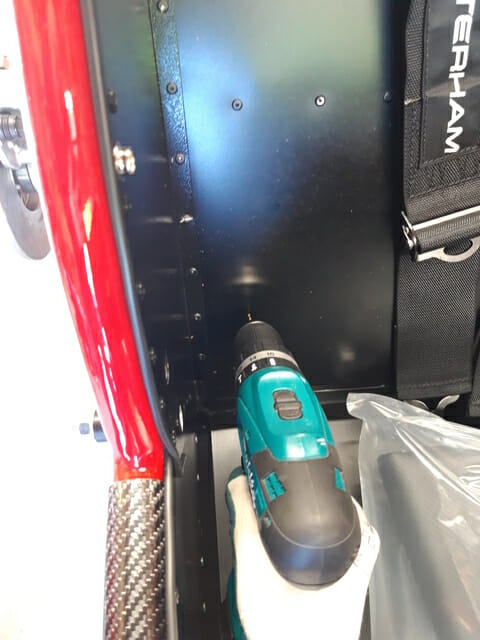
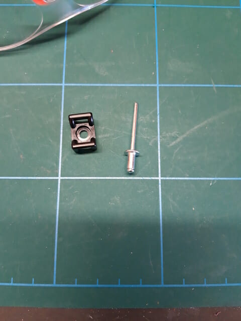
Once done widen this out to a 1/8in hole with an imperial HSS drill bit, then get a cradle clip and rivet to the car body. This will be used to hold the speedo wire up and stop any snagging on ARB.
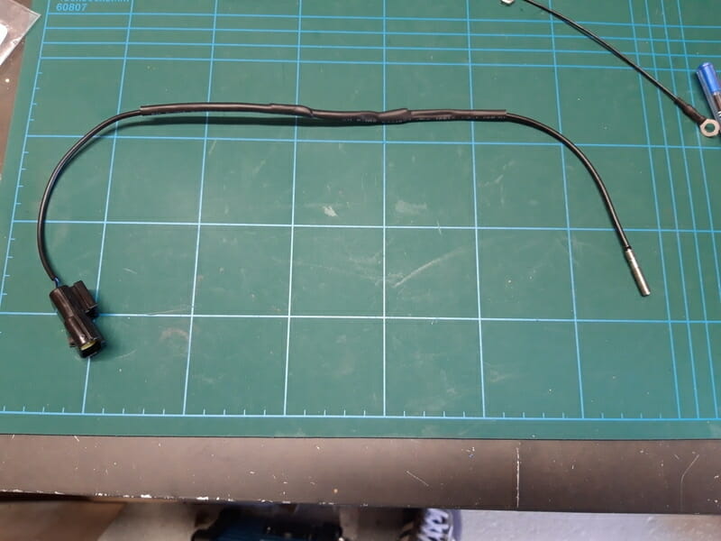
I started by putting some heatshrink over the speedo wire for addition protection as it was quite flimsy. I do not know if it will help or not, but figured it would make sense and several other blogs seem to do it.
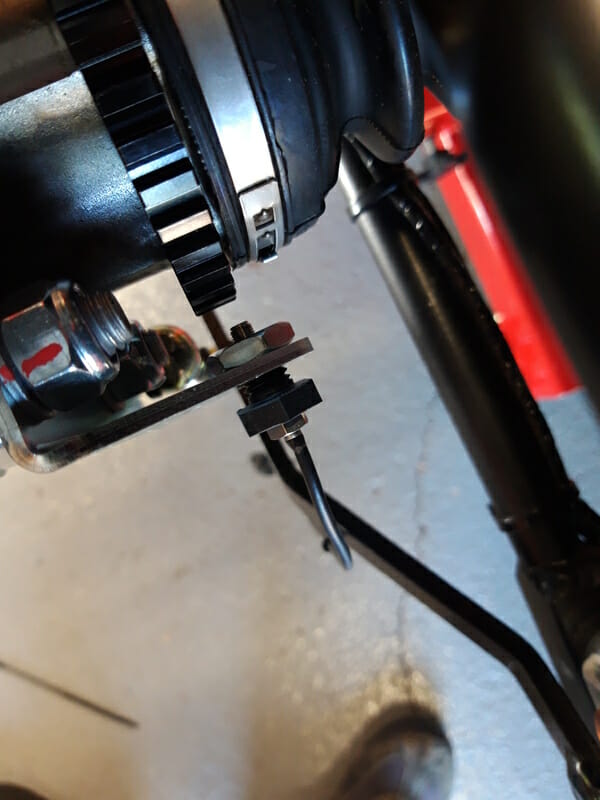
Then run the components onto the speedo itself and fit in the relevant hole on the drivers side. Adjust the black nut until you have the right distance from the cog, similar to the below :
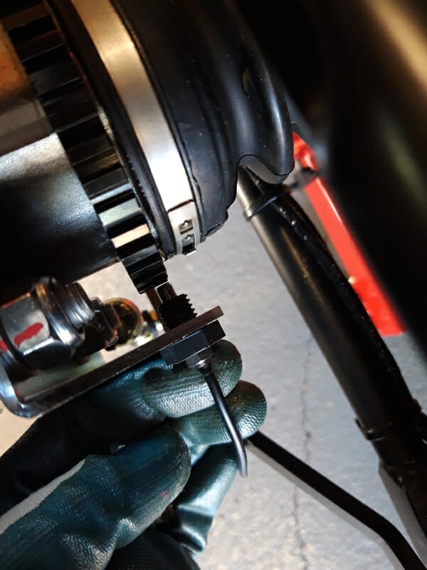
Once you have it set right, pull it out a bit and add the final lock nut (grey steel nut in the pic below) and tighten that locknut up to get the speedo itself nice and close to the cog to get a good reading.
Don´t secure any cables yet as you need to do the earth mod.
Earth mod
There is something called an earth mod on the caterham speedo. Because the earth is at the end of a long wire, you can have situations at higher speed where the speedo needle will bounce around somewhat. This is apparently improved if you earth the speedo much closer to the speedo itself. This is optional, but I decided to do it. Heavily borrowed from 420 detailed build blog for this bit!
You need to remove the plugs from the econoseal adapter. To be very clear, it is the econoseal adapter which is at the end of the car wiring loom that is being modified here, not the econoseal adapter attached to the speedo itself!
You need to get the wires out to do this. This is easiest if you have a special tool, but is also possible if you have a very small screwdriver.
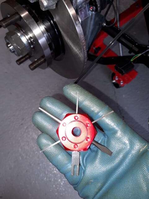
First take a picture of the adapter so you can be sure to put it back together in the correct order!
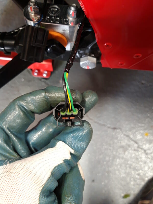
Now you need to remove the yellow cover – ping this off gently using a screwdriver or the tool.
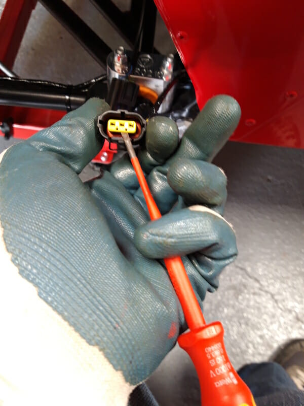
Then get the tool and insert it below the plug, as shown in the picture.
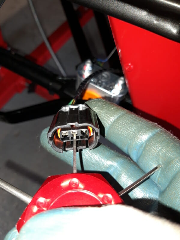
Once you have the tool in place, you are trying to flick up a little piece of plastic inside the adapter itself, underneath the metal insert. You do not need much force at all, there is really a knack to it and it is very hard to describe. Gently push the tool up and slide it back until you get some resistance, then give it a bit of wiggle and pull very gently on the back of the cable you are trying to get out at the same time to try to pull it out.
Make sure you pull the cable gently, if you do it too hard you may pull the wire clean out and then it will be a right pain. Remove all three wires. Then bend back the existing earth wire (black) and put some heat shrink over it.
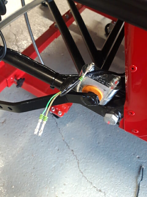
Now prep the new earth wire. You can attach anywhere, but I decided to use one of the bolts that is securing the ARB bracket to the chassis (thanks 420 detailed build blog). If you go down this route, you may need to drill out the connector somewhat and do this with caution as it can bend or break. That is the hack, the correct way is to replace the ring connector with a slightly larger one.
Once ready, remove the front most bolt on the RHS ARB bracket, before adding the connector and then tightening back up.
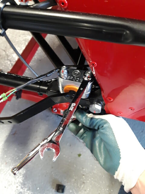
Make sure you torque the ARB bolt properly again to 14Nm once you have fitted the earth. Now plug this new earth into the econoseal connector. To plug in to the econoseal connector, just slide in the metal connector. Make sure that you have it the right way up – again the key with these connectors is not forcing it!
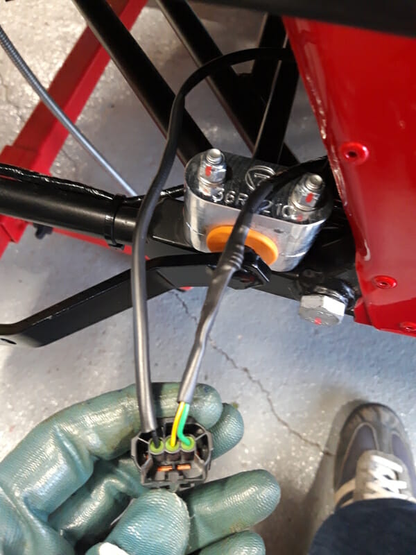
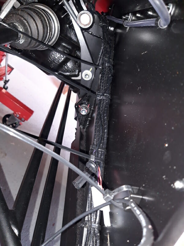
Use zip ties to secure the speedo wire to the radius arm, leave some slack to allow for travel in suspension. Then make sure you tidy wires and ziptie down on the chassis.
Fitting brake hose
At this point I went ahead and fitted the brake hose. I would have liked to have done this when I fitted the de dion tube, however I was missing the two lock nuts needed to connect the brake hose from the car body to the de dion tube. It seems that a few other bloggers have had this issue as well. Unfortunately due to coronavirus Derek wasnt able to get any bolts out to me and he didn´t know the spec of the nuts of the top of his head (cant blame him!!). I measured the hose up and ordered some 3/8 in half height lock nuts from caterham parts because it started to hold up my build. These turned out to be exactly the right size.
Start by taking some spare 8mm hose, cut a length which is equal to the length of the braided section of the brake hose. Then as before, trap it into a workmate and very carefully run a sharp stanley knife down the middle. Make sure that your femoral artery is not anywhere near where the knife will come off at the end!!
Once done, because I was fitting this after putting the back together, I found a lot easier to fit the hose on its own first. screw on the locknut onto one end of the hose as far as it will go. Then screw this end of the hose into the top of the T piece on the de dion tube. Tighten up by hand as tight as it will go, but do not force it. Then twist the locknut until it is tight against the T piece. These two nuts work together to stop it coming undone. Then at the top, run the hose through the large plain washer as indicated by manual, then through the chassis, then thru the anti vibration washer, then attach locknut and do that up about halfway. At this point there should still be a bit of ´wiggle´ on the top of the hose to help you align with the copper brake line on the car. Use this wiggle to line up and slowly screw the copper brake line onto the hose – do not force as you do not want to thread it. Once you have it successfully centered, do it up a few turns, then tighten lock nut against the body before tightening the brake pipe.
Once all done, put the 8mm hose onto the brake hose, and secure using zip ties.