You get supplied with two rear lights which look identical. The lights are essentially a rubber boot to compensate for the angle on the rear wing, a metal plate with wiring which sits in this rubber boot, and a lens which is screwed on top. I have the clear lens pack, but won´t fit these until after the IVA. I will fit the standard lights provided.
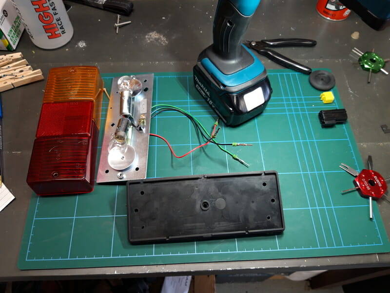
You can change the side of the car that the light will fit on by simply rotating the metal panel which rests in the rubber boot upside down. You can tell the indicator light as the bulb will only have one filament in it, and the wire leading to it will be green and purple.
The brake light bulb has two filaments in it (one for rear lights and another for brakes). On the LHS, the earth wire rests at the bottom of the plate when it correct position. On the RHS, the earth wire rests at the top of the plate because it has been flipped upside down to get the indicator light on the correct side.
It is an IVA requirement to have the wiring in the rear wing totally insulated. The existing insulation on the wires is quite short. I disassembled the econoseal connector and fitted new heat shrink. The first time taking one of these connectors apart is a bit of a pain, but once you get used to it, it is quite easy. I used some terminal tools.
Important – before removing anything, draw yourself a clear diagram so you know which terminal goes back in which socket. You can also work it out from the corresponding plug, but much easier to draw yourself a map now.
Here is a brief guide to taking an econoseal connector apart, for those who don´t know :
Start by removing the yellow block – the terminal tool or some pliers can do this :
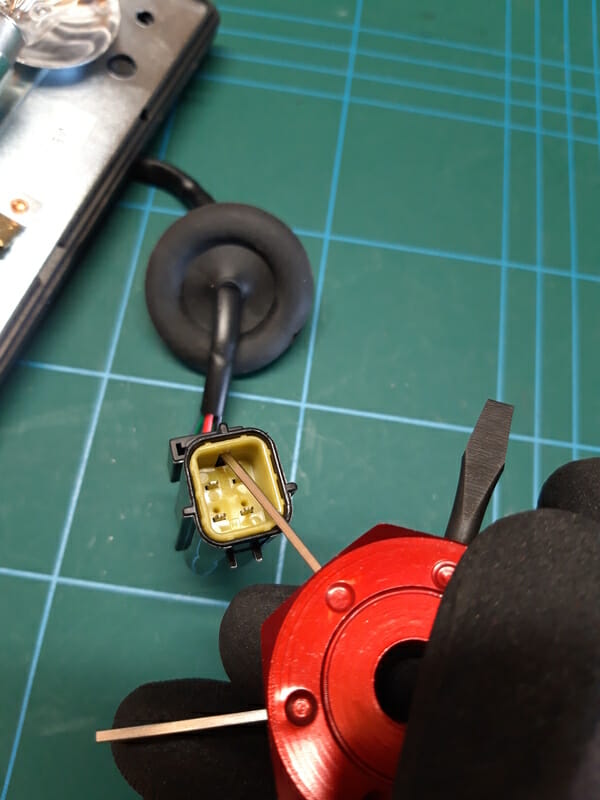
This leaves the terminals exposed :
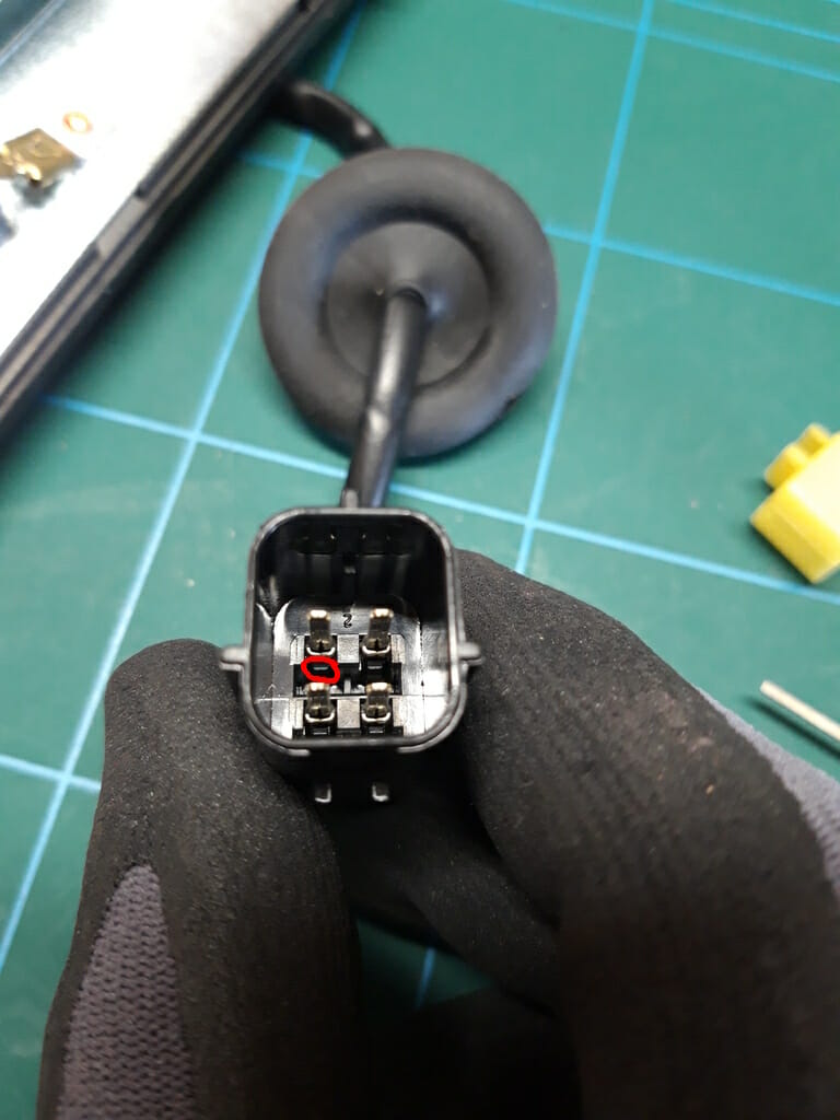
Underneath each terminal if you look very closely you will see a very small plastic tab. In the above picture, I have circled one of these tabs with red. These hold the terminals in place.
Using the terminal extraction tool, you need to use one of the thin blades to slip between the terminal itself and the plastic tab. Do this quite gently and give it a wiggle, while at the same time pulling very gently on the wire, and it should give way as you can pull the wire out. There is a real nack to it – once you have done it a few times it will get very easy to do.
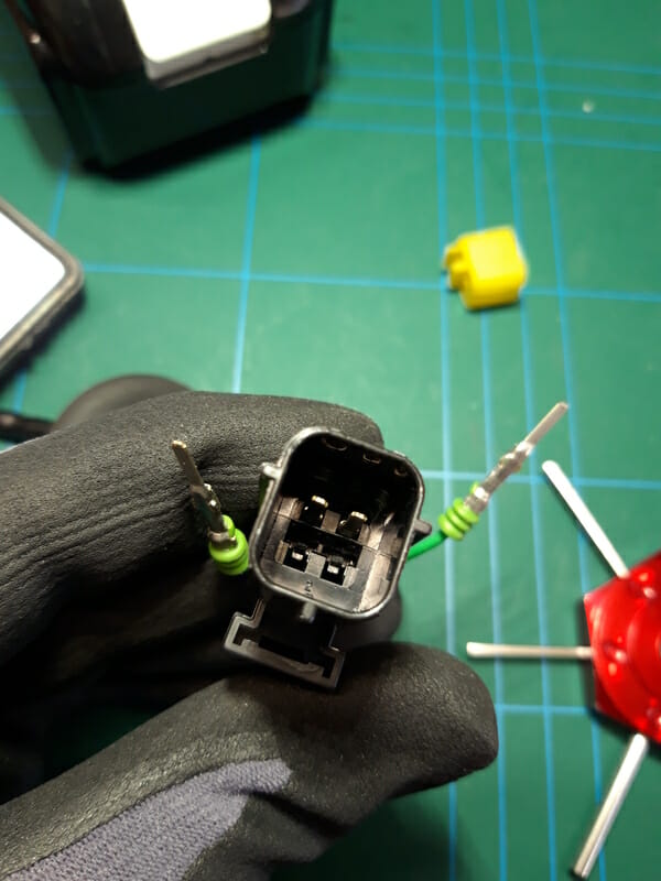
Once all terminals have been removed from the connector, remove the rubber boot. Use the rubber boot on its own to drill the holes in the rear wing.
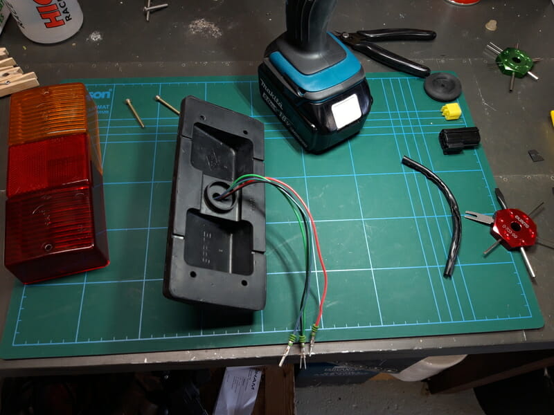
I am going to take the 420detailedbuildblog approach and use bolts instead of the supplied fixing screws. This has the additional benefit of making fixing much easier. I purchased Flange Hex Socket Stainless Steel A2 M4 bolts. M4 x 30mm for the bottom and M4 x 40mm for the top. Before building this car I had no idea you could get so many types and varieties of nuts and bolts. I used these with some M5 washers (due to slight angle from arch) and M4 nylocs. The benefit of this is its a lot easier to take lights on and off – I also didn´t like the idea of sharp screw heads inside the rear wing where I could end up catching my hand on them.
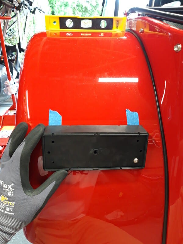
The bottom inside hole has been pre-drilled by caterham to get you started. Apply masking tape where you are going to drill, offer the boot up to the wing and put a bolt through the bottom pre-drilled hole to help hold the boot in place. Don´t tighten up too much.
Put a spirit level on top of the wing to check it is level. You want the top of the boot to be at the same angle as the top of the wing. As my wings were both level I aimed for this.
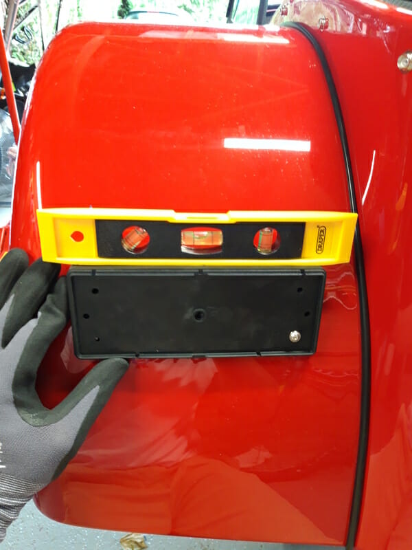
Now drill through the other bottom hole. Make sure that the drill is level as you drill through – I drilled through the hole in the boot, nice and slow, just to make a mark, before removing the boot to finish off. As usual when drilling fibre glass I wore my mask. Now put the boot back in place, with bolts going thru the two bottom holes. Now repeat this process twice for the top two holes. Each time, check the boot is level before drilling the next hole.
Once this boot has been fitted and looks good, remove the boot again and the masking tape. Reassemble the brake light on the bench, this time add heat shrink to all the wires once you have pushed them through. Make sure the light is the correct way up (single filament for indicator on the outside). Don´t forget the grommet and reattach the terminals to the connector. Now fit the light to the car. On the inside, make sure you add a P clip to the inner most bottom bolt, this will be used with a zip tie to hold the heatshrunk wiring out of the way. Now attach the econoseal connector to the connector which comes out of the car – if they are not peaking out have a hunt around just inside the bodywork.
Finally, push the grommet in place. This can be a bit tricky but they go in eventually.
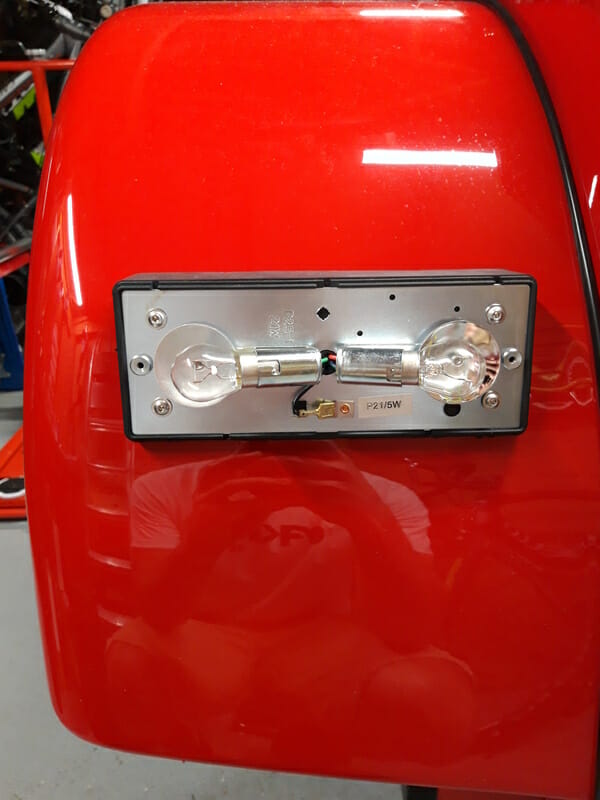
Repeat for the other side.
Note – surprisingly after fitting the rear lights this may have fixed my issue with the oil pressure gauge, which is now giving me a reading. Unfortunately, my rear brake lights are stuck on! I worked out this is because of the rear brake light switch sticking. To access this, remove the pedal box cover. The rear brake light switch is highlighted in this picture –
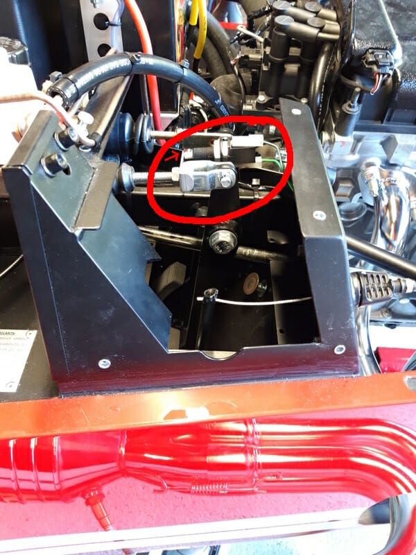
When you push the brake down, the metal piece moves back towards the driver. When the pressure is taken off the switch, it causes the brake lights to go on. I pushed this switch in and out a few times which seemed to help. Whether that works long term lets see. I notice that the switch has threads on it so you can change position. Unfortunately, the move which makes sense is not possible as the switch is already at the limit. Perhaps a pedal adjustment may be needed. I will bring this up for PBC, although maybe driving around with the brake lights around is a good tactic to stop anyone getting too close!