Full plumbing and electric for a Caterham 310R build
Before proceeding, check that you have an M8 caphead bolt, two M8 washers and an M8 split washer for the battery to chassis connection. While you´re at it, check you have the nut for the submarine earth tag, two bolts and nuts which fit the battery terminals and a screw for the p clip on the front of the engine. Most of the components you need are in the cooling box. Some may be in the boot of the car.
This is quite a lengthy post as it covers pages 46-84 in the manual.
Hose inventory:
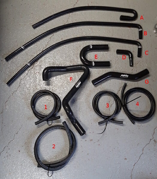
- Main silicone hoses, all will need trimming and cutting except two.
- A : Two parts. U shape will be for Submarine to engine. Remaining pipe is for oil filter to upper heater valve.
- B : For submarine to lower heater valve.
- C : T Piece. Use the bent section for rear section of T Piece to oil filter. Use remaining straight hose for front section of T piece to expansion tank.
- D : For T piece to Engine
- E : For connecting two water rails on rear of engine.
- F : Lower radiator to engine. Does not need trimming.
- G : Upper radiator to engine. Does not need trimming
- All of these hoses are clearly marked with the diameter on the hose
- 1 : 1/2inch hose – not needed.
- 2 : 5/8inch hose – also marked ¨Heater Hose¨ – cut two lengths for connecting heater to heater valve.
- 3 : 3/8 inch hose – to be used as protective cover for the clutch cable
- 4: 5/16inch hose – runs from rear of engine to expansion tank
This is one of the orders you can take. In general, you don´t want to be putting anything in place when you have things you need to put in place beneath it. The below is for a 310R SV with Ford Sigma 1.6 engine, with a master battery switch.
The main engine bay is mostly fine, the gap between the battery and the engine which is very busy. Manual page number included where applicable, N/A where there is no manual reference. Use plenty of zip ties as you work to keep it tidy. Do not pull zip ties too tight until the end and do not trim tails on the zip tie until you have finished to avoid cutting your hands.
With hoses, using some Holts rubber lubricant makes any fitting vastly easier. Where you are connecting hoses, make sure you push the hose all the way to the stop, which will be a little piece of metal or plastic on connection that you are pushing the hose onto.
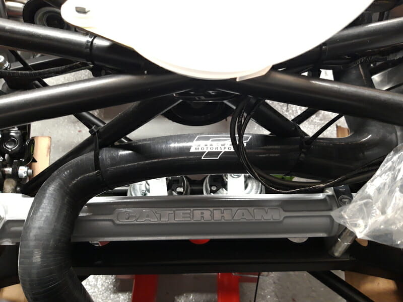
1. Connect lower radiator hose. Pages 46/47. Hose F. Use 30-40mm hose clips on both ends. Use zip ties to secure this to the chassis above the steering rack, you do not want it resting on the steering rack.
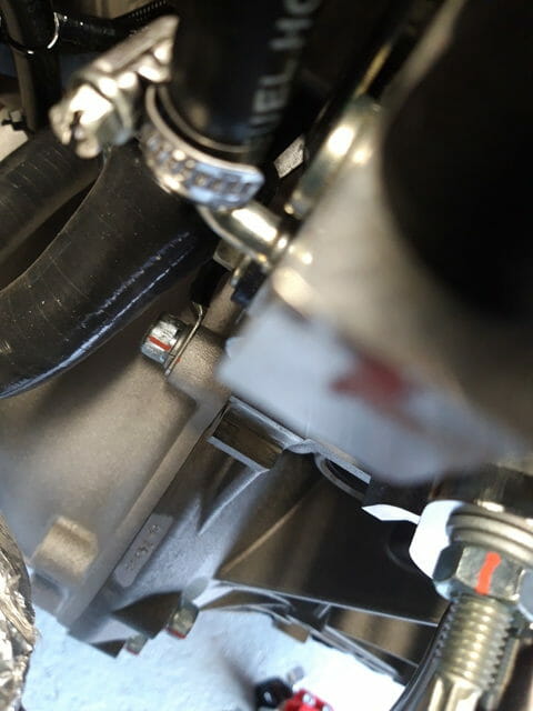
2. Battery cables. Pages 76-79. Do NOT connect these cables to the battery yet. There will be two red cables coming out of the transmission tunnel which have been marked B (for battery) and S (for starter motor). Route the B cable just below the battery to the Driver side of the battery. Route the S cable along the chassis member and then down to the starter motor. Secure loosely with zip ties. Now choose one of the top two bolts securing the bellhousing to the engine and undo the bolt. Secure the long black lead to this bolt, before retightening to 47Nm. This will connect the battery to the engine/bellhousing.
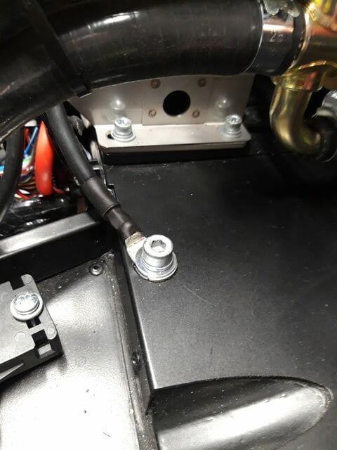
Now take the short black lead (if you have two long black leads, contact Derek for a short replacement). This is also called the earth strap. Use the M8 caphead which you may also need to get sent out to you, along with an M8 washer below the strap, an M8 washer above the strap and a split washer to secure this black cable to the chassis. These two black cables need to the routed to the passenger side of the battery.
3. Clutch Hose. Page 74-75. Take the 3/8 inch hose, measure length from the base of the clutch cable to the top of the clutch cable and cut the 3/8 inch hose to length. Now take a WorkMate or similar, secure the hose in the workmate and move a sharp stanley knife along the hose in a controlled fashion… needless to say be very careful doing this, especially at the end. Once done, wrap this onto the clutch hose, and secure with 5-6 zip ties. Again, do not trim the zip ties yet as you will catch your hands. Also do not secure the clutch hose to the clutch yet, do this later as the flexibility helps for now.
4. Connect chassis loom to engine loom. N/A. This is the big black plastic plug with grey handle, connect this, pull the handle down tight and then secure it to the cables running underneath the battery with a zip tie very loosely for now (can tighten later)
5. Run Engine loom cable to starter motor. N/A. On the engine loom, identify the cable for the starter motor. You will see a white wire with red stripe ending with a ring. This is the start of a very long cable which runs to just above the oil filter on the engine. Take the connection where this cable meets the engine, just above the oil filter, and gently disconnect it. Get the long cable into the gap between the battery and engine, then thread the whole length of cable between the engine and starter motor, (following the other grey sheathed wire which terminates just below the starter motor).
Once done, you can reconnect this long cable to the engine, and hopefully you will have just enough slack to connect the white wire with red stripe (marked cable 5 in manual) to the relevant terminal on the starter motor. It may be a little tight and require you manipulating the cables in the gap between battery and engine to get this to fit. If this does not work, try another route. After it has passed the starter motor, secure this long length of cable to the chassis tube, then the LHS engine mount using zip ties to keey a neat cable route.
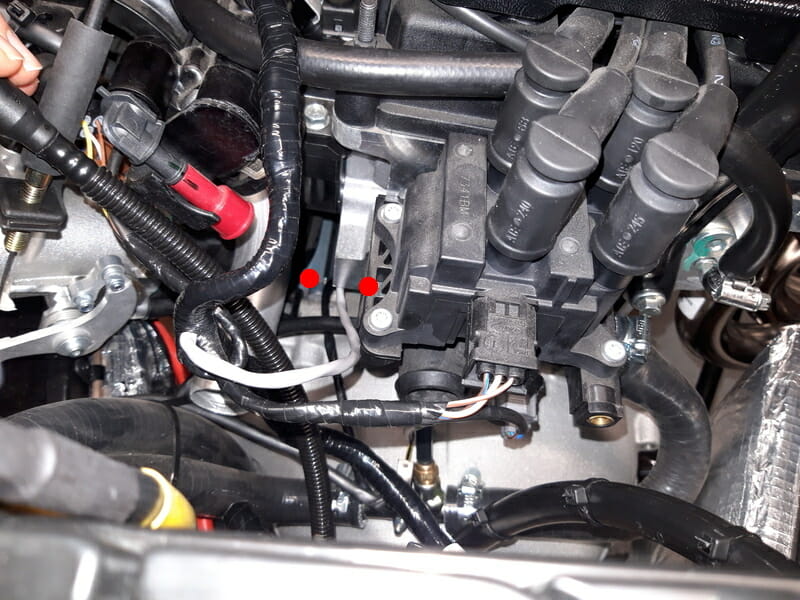
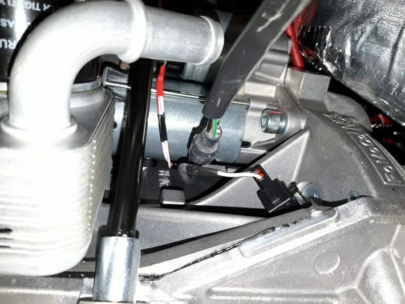
6. Wire starter motor. Page 170-171.If you have the master battery switch, you will not have the two brown wires coming from the loom. Just FYI, the battery switch itself is located just underneath the windscreen on the exterior of the car on the drivers side. There is a red key in the box in the boot. Turning this key kills battery. Connect the red wire, the white wire with red stripe, and the sheathed cable from the alternator to the relevant points as per the manual and tighten nut.
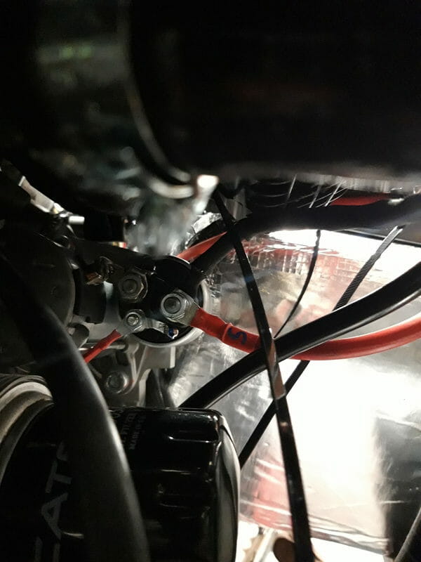
7. Submarine. Page 52-59. The temperature sender and earth tag should be attached to the wiring loom already. Make sure you have the nut for the earth tag, mine was missing. Start by connecting the submarine to the wiring loom, using a drop of loctite as per manual on the temperature sender. Once done, tighten the sender gently, do not over tighten it, and tighten the nut. Be careful that you don´t accidentally drop this nut into the bellhousing, or you will be livid!
Now trim hose A and B as per page 53 in the manual. Once done, follow page 57, connecting the small U shaped hose (cut from hose A) to the engine using a 25-35mm hoseclip (not 17-25mm which is what manual says). Connect the other end of this short U shaped hose to the correct end of the submarine (see page 55 to verify which end of submarine goes to which end of hose) and secure with 17-25mm hoseclip.
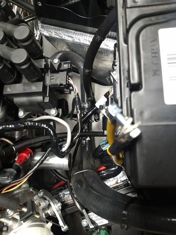
Then take the L shaped hose that you cut from hose B, and secure to the other end of the submarine again using 17-25mm hoseclip. This hose from the submarine runs up to the bottom heater valve – page 57 of the manual is incorrect. Don´t trim the hose until you have completed step 8 below.
8. Oil filter to heater valve. Page 80/81.Take the straight remains of hose A, and run this from the oil filter to the top heater valve, routing the hose between the bellhousing and the heatshielding on the passenger foot well. Secure to the oil filter with a 17-25mm hose clip. At the top, in the engine bay by the heater valve, you should now have two lengths of hose showing. Get them into position ready to connect the hose from the submarine to the bottom of the heater valve, and the hose from the oil filter to the top of the heater valve. Cut these hoses to length, and connect to the heater valve, securing again with 17-25mm hose clips. .
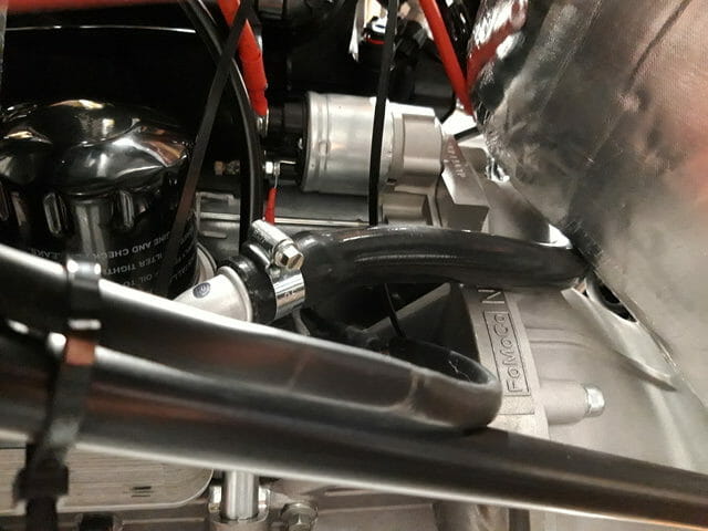
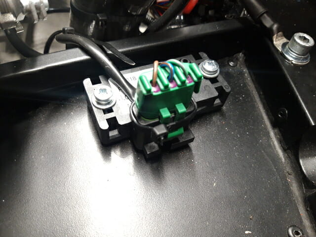
9. Attach ecu cable. There is a green cable which attaches to just on top of the passenger footwell – secure this cable and use a zip tie to hold connection out of the way as per picture.
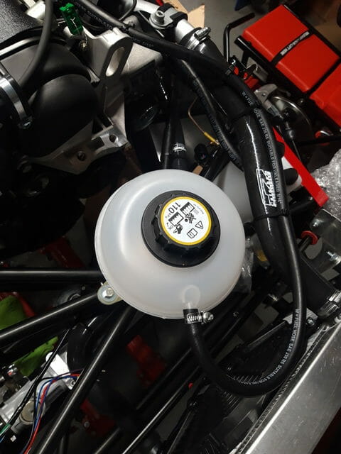
10. Attach expansion bottle to chassis. Page 62/63. As per manual, gentle with any plastic as you don´t want to snap it. I was missing the plain washer between the expansion bottle bracket and bolt, only a split washer there.
11. T piece hose assembly. Page 66/67. There is a sturdy blue plastic t piece in the bag in the cooling box. Trim hoses C and D as per page 67 in the manual. As a sanity check my measurements – expansion tank to t piece 38cm of straight hose. T piece to oil filter, using the L shaped section of hose C, 8cm x 36cm. Hose D was trimmed to be 9cm x 9cm measured on the outside of the L shape. Note the hose clip for hose D on the engine is 25-35mm. All other hose clips used 17-25mm. This is very tight, but can be done.
When attaching hose D to the T piece, make sure the hose clip is in place first before pushing T piece on. I then squeezed the hose clip very tightly and made sure the bolt in the hose clip was pushed to the top of the mount, before tightening with a 7mm 1/4in socket.
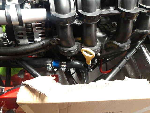
Hose clip technique – when putting the hose clips on the other two T piece terminals, it can be quite tight. I used Holt´s rubber lubricant liberally to secure the hoses to the T piece. I then loosened the 17-25mm hose clips as much as possible, then fed them onto the hose from the other end of the T piece. Once I got to the tight piece I rotated the hose clip as I pushed it on. Note the hose clip has a catch on it, it only wants to be rotated in one direction, it will dig in if you try to rotate the other direction. Once in position, I then squeezed tightly, making sure that the bolt was as high as possible to allow it to catch. There´s a bit of a nack to it but once you have done one the other is easy.
12. Upper radiator hose. Page 48/49. Fit hose G as per manual, using 30-40mm hoseclips to secure each end.
13. 5/16 expansion bottle hose. Page 68/69. Quite tricky at first – use a 4mm drill bit to drill a hole in the front engine lifting point. Secure a zip tie cradle to the this using a rivet, Take your time doing this and drill the narrowest point for ease. Then route the 5/16inch (hose 4 in diagram) from the rear of the engine (secured with 8-15mm hose clip), behind the connections on the read of the engine, along the top of the engine, underneath the hose for the oil catch tank, through a zip tie secured to the engine lifting point, along the top of the upper radiator hose, before bending back and securing to the driver side of the expansion bottle with a 8-16mm hose clip. Use zip ties liberally all along this route.
Exercise caution when you are tightening the hose clips as you could easily damage the plastic on the expansion bottle.
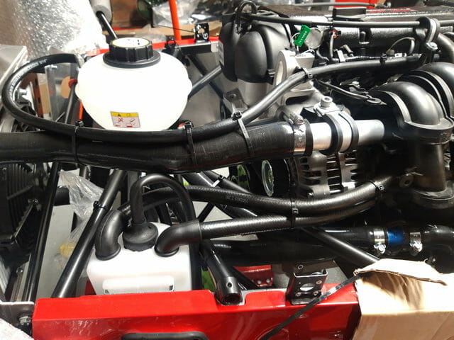
14. Oil catch tank. N/A. Take the oil catch tank, and two elbows from the pack which comes in the cooling box. Place the oil catch tank in a vice, and put some masking tape on top of it. Offer up the rubber elbows to the top of the oil catch tank and trace around them with a pen, making sure you have enough clearance. Next, use a 19mm wood cutting drill bit to make two holes in the top of the oil catch tank. Clean out all debris. Next, fit the oil catch tank to the bracket at the front of the car which was installed earlier.
Now run the two 1/2 inch hoses which are already prefitted to the engine to the rubber elbows, making sure you don´t mark them too short, use some masking tape to mark the hose where you want to cut. Then using a cutting matt with the manual or similar, cut the hoses to length. Use some holts rubber lubricant to push the hoses inside the rubber elbows, then push the rubber elbows into the oil catch tank – very similar to fitting grommets. Tidy up and secure the oil catch hoses together with zip ties also.
15. U shape hose. Page 60/61. Connect hose E as per manual. The wiring loom should be neatly inside the U. Secure with 30-40mm hose clips.
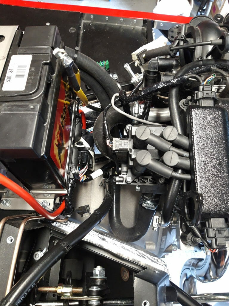
16. Connect fuel line. Page 70/71. Making sure it is snag free and routed inside the U shaped hose, connect fuel line to engine.
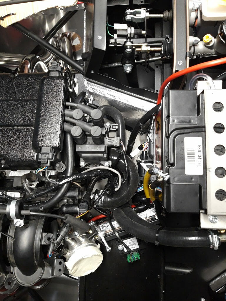
17. Connect throttle cable. Page 72/73. Remove pedal box screws and pull off pedal box. Make careful note of what screws you have removed from where. The one between the pedal box and battery is particularly tricky to access. The cable routes from the passenger side of engine, around the front to the driver side pedal box. Make sure you secure neatly at both ends and use the P clips, facing inwards, to route the throttle cable. When you bring the throttle cable into the throttle box area you will need to make some adjustments to the top of the throttle pedal. Use a screwdriver to prise apart the top of the pedal
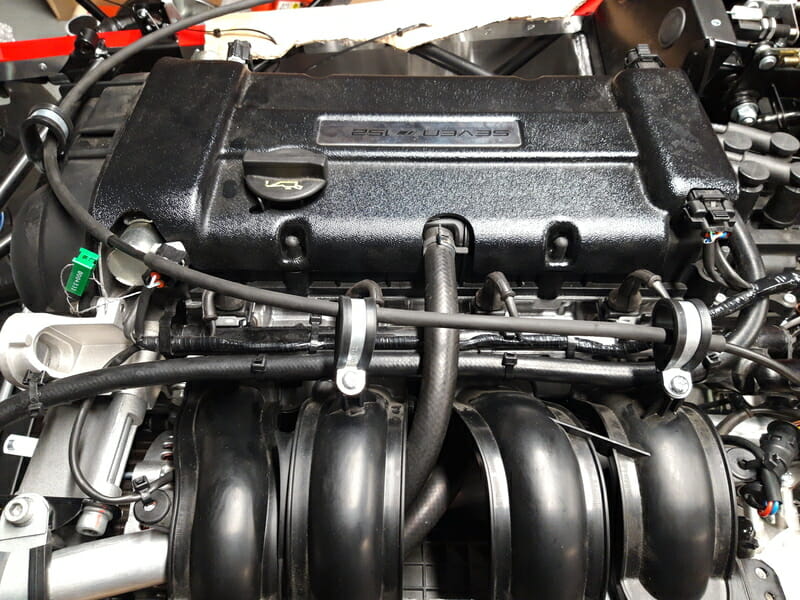
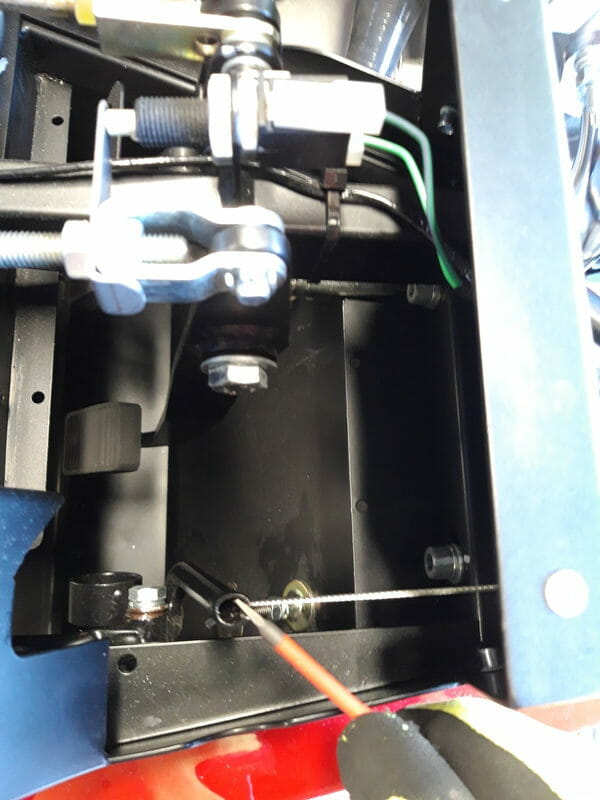
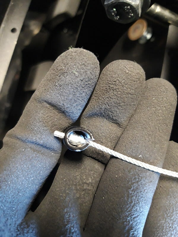
Once done, you need to use pliers or monkey grips to close the top of the throttle pedal up again so that this doesn´t easily come out – you obviously don´t want this falling out on a bumpy ride!
Finally, open up some silicone sealant and put a dab on top and close up the pedal box. When you close up the pedal box, good idea to start with the trickiest bolt which is between the pedal box and battery, and then do the screws which are securing the brake pipes down.
There is a lot of discussion on various blogs and forums about loose throttle cables and some travel. From what I could tell, this would be sorted out by the throttle stop at the bottom of the picture looking down, and also by the bolt mounted to the chassis just inside the pedal box which looked like it would appropriately limit travel in the trottle. I believe this gets fine tuned at PBC so I have left it alone for now.
18. Connect clutch. Page 74/75. once pedal box has been put back in place, secure the clutch – remove the bright yellow plug to begin with
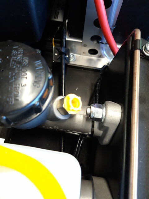
Underneath the bright yellow plug, that you can discard, is an adapter which is shown in the photo below. This adapter is also not needed. All you need is the bolt which goes through the end of the clutch cable (this has two holes in it to allow fluid to move through the clutch) and the two copper washers.
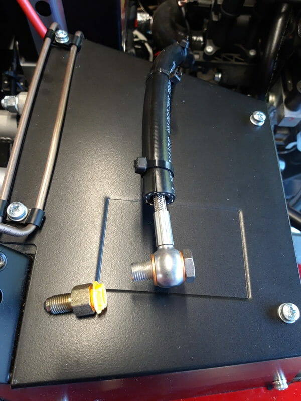
Then fit to the clutch reservoir, being careful to center the copper washers. There is no torque value supplied, I just did it up fairly tight.
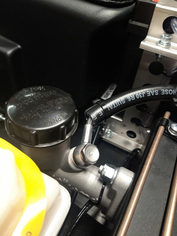
The clutch will need to be filled and bled, along with the brakes. Both clutch and brakes take DOT4 Brake fluid, which is pretty nasty stuff if you get it on your skin, or indeed the car paint. I intend to do this job towards the end of the build when I add all fluids to the car – I have left everything empty for now, except the engine and gearbox which are pre-filled. So I will need to fill and bleed clutch and brakes and add coolant to the engine.
That´s it. Not connecting the battery at the moment to avoid electrocuting myself later! I will connect everything up at the end.
