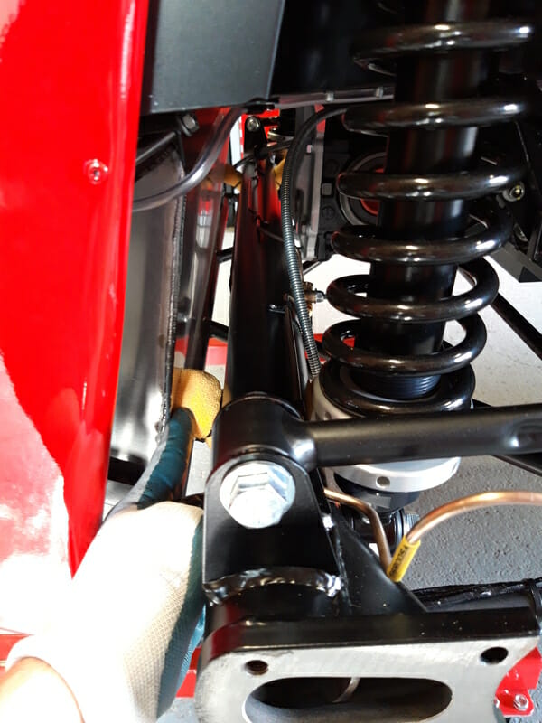
Radius Arms :
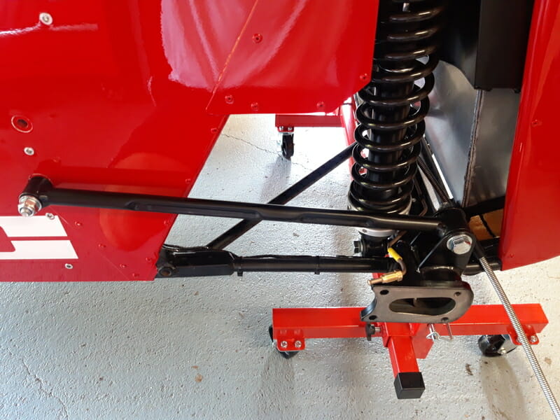
The radius arms connect the car body to the de dion tube. I have the R spec, which as per the manual has a lower mounting point on the main chassis vs the S mounting point. The S mounting point is drilled out and ready to go…. Unofrtunately, the R mounting point is not – it is blocked inside the car body by a panel which hasn´t been drilled.
Now it isn´t an absolute requirement to use the lower mounting point, and other builders have used the S mounting point on an R spec car, however I decided I wanted the lower mounting point. Starting with a 3mm HSS drill bit, drill into the center of the hole from the inside of the car. Work up to a 10mm drill bit. Once 10mm has been drilled out, get a HSS wide bit and drill the rest out, I very fortunately found a 18mm Makita bit which fit just right.
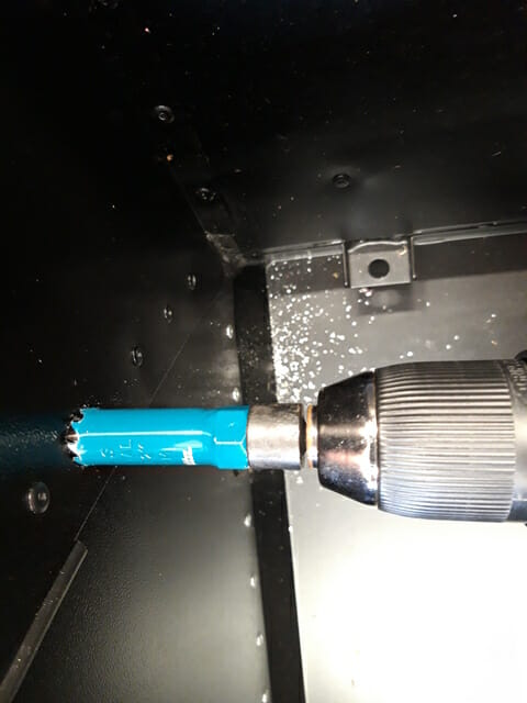
Remember when drilling not to press too hard. You aren´t drilling through an inch of metal here, this is removing a 2mm thick small circle of panel, so be very careful you don´t push the drill bit too hard into the car body.
Plenty of vacuum on the hole to get rid of any metal shards there and in the cockpit. As always when drilling I used a mask.
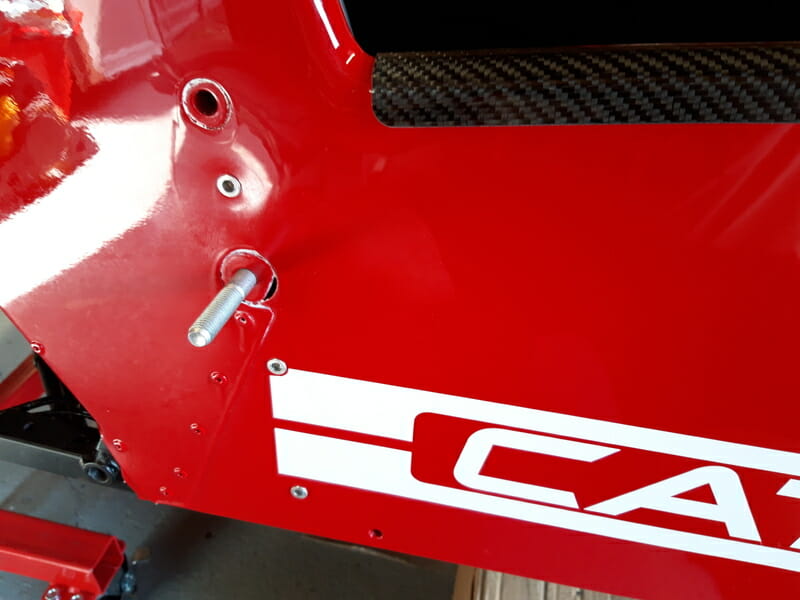
Once this has been drilled out you should be able to get the relevant bolts through the hole, this may need a couple of taps on the nylon hammer and some turns with the ratchet as well, but eventually the bolts should comfortably slide in and out. Put these top caphead bolts in, with some copperslip, from the inside and place the upper radius arm point on them.
Then secure the back of the radius arms to the de dion tube. You may find that the point where the radius arm meets the de dion tube is too tight. If this is the case you can use caliper tool to widen out just a fraction. If you do this, go slowly and in increments, widening a bit, then removing and trying again, before widening again if it still isn´t wide enough.
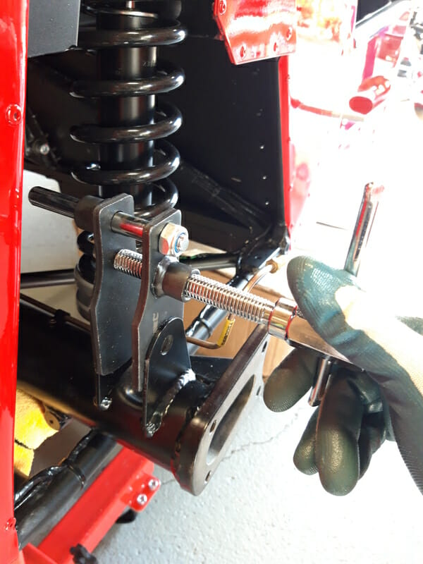
Once wide enough, you will be able to slot the radius arm into position on the de dion tube. Add the rear bolt, with some copper slip applied, and tighten up with a ratchet. Again do not torque yet.
A Frame :
The A frame centers the de dion tube and prevents lateral movement. Get the A frame into place and hold in place with pin punches. There is cabling running along the top of the both sides of the chassis, you need to be careful that you don´t damage this. You also need to make sure that the A Frame is the right way up as per photo (and manual) :
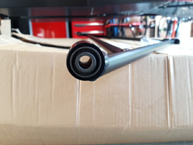
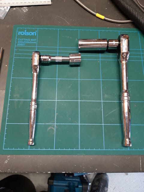
Start off by securing the A Frame to the de Dion tube at the back of the car with the rearmost bolt. (This is also the future jacking point.) Copperslip the bolt and push through from the LHS. Make sure that you use the two nylon washers between the inside of the A frame and the de Dion. The bolt and the nyloc nut are imperial, use 3/4 in sockets to tighten up. The bolt and nyloc nut are recessed and need fairly thin sockets, luckily the Halfords Advanced ones fit fine.
Make sure you start with this rear bolt or you will be wasting your time doing alignment later!
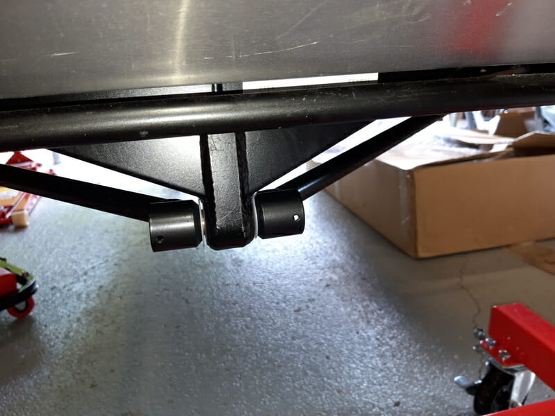
Moving towards the front, there are two mounting points where the A frame meets the chassis. There is a gap at these points between the A frame and the chassis, and this gap needs to be filled with heavy duty washers, or the A frame would be placed under too much stress when driving.
The objective is to center the De Dion tube relative to the chassis, using the A Frame. To assess how centered you are, you need to measure from the edge of the chassis tube to the outside edge of the de dion tube on each side, this is easiest using a set square. These measurements should match as close as possible (hopefully within 1mm) on both sides. The magic number on my SV chassis was 85mm on each side.
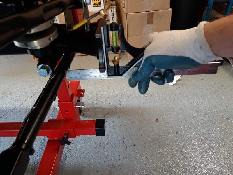
I would suggest 3 washers on one side and 4 on another (this was also Derek´s input). I used 4 on RHS and 3 on LHS.
Hold both front mounting points to the chassis using pin punches. Starting on the side with the worst alignment, pass up the stack of washers from underneath (in my case LHS, 3 washers). There is enough wiggle room to easily get these into position, and hold them in place with a pin punch – the washers should be fairly well centered.
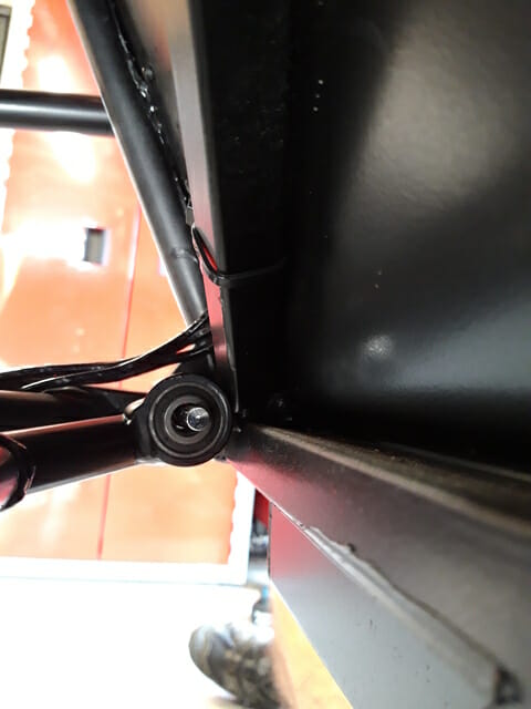
Now move to the other side. Space will be tighter now, but it is surprising how many washers you can fit in, it just comes down to technique. Pull the A frame down slightly, and take the last set of washers (4 in my case, on the RHS). With this stack of 4 washers, make sure that the chamfered washer edge at the top and bottom of the stack is facing outwards. Then place the washers against the A frame. Pull the A frame up slightly, you should be able to trap the other end of the washer stack against the chassis. You should be in a position where you can take your hand away and the washers will not drop of the ground. It will look like the washers are not going to fit in the gap.
However, you can pull the A frame up and wiggle it around, and you should find that doing this slowly you can pull washers up. Keep pulling the A frame up until when you look through the chassis, the centers of the washers are visible. Then get to work with your pin punches to align the washers. Once this side is aligned, go back to the other side, back up and the washers should be dragged up as well. Keep pulling up until you can see the centers of the washers from the outside of the car, before getting to work with pin punches. As usual start with the smallest pinch punch and work your way up in size to the largest, slowly pulling the washers into alignment.
Once both sides are aligned, take the bolts and apply copper slip. Now pull out your pin punch, and put the thickest pin punch in from the inside of the car.
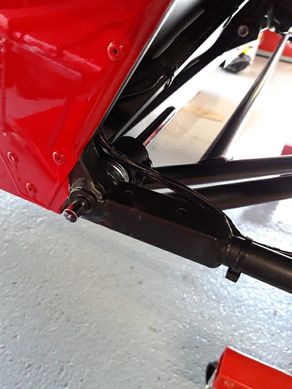
Push the bolt in from the outside, and tap it a few times with the nylon hammer, not too hard. Apply very slight pressure to the pin punch, so that as you tap the bolt through, it is pushing against the pin punch. This stops any washers falling down. Hammer all the way though, then secure with a washer and nyloc nut. Repeat this on the other side. Do not torque yet.
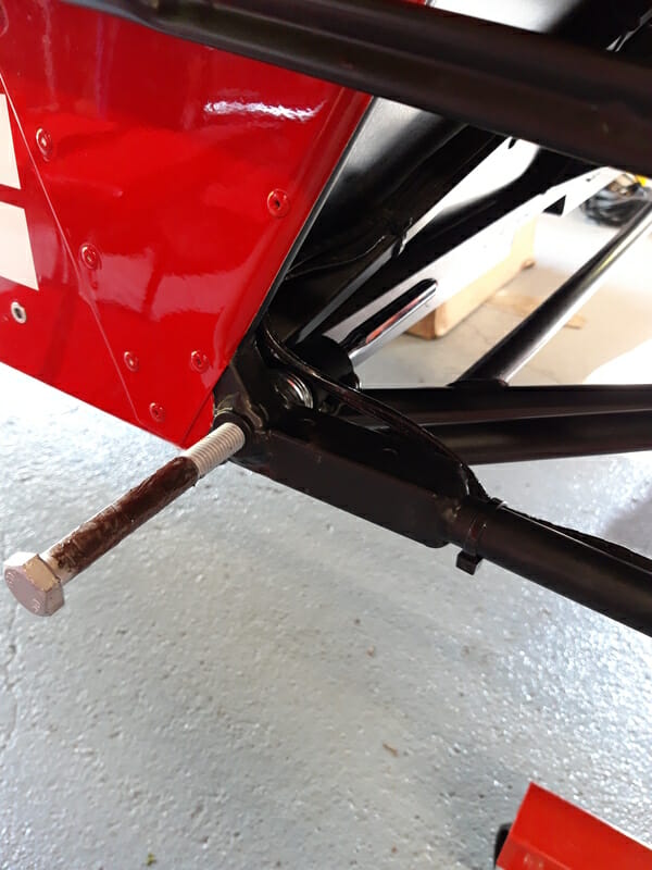
Note – Reaching the correct number of washers was quite frustrating. When I put washers in place temporarily using pin punches, the measurements would look good. I would then add the bolts and after I would get a different measurement! I suspect the my LHS mounting point was very slightly bent which threw things out of alignment somewhat. This table below shows the different measurements I achieved to give you an idea of tolerances. Measurements are from chassis to de dion tube, using calipers or set square and are approximate. Plenty of swearing here – don´t give up too early! :
| LHS Washers | LHS Measurement (mm) | RHS Washers | RHS Measurement (mm) |
| 4 | 82 | 2 | 86 |
| 3 | 83.6 | 3 | 86 |
| 2 | 86 | 4 | 83.6 |
| 4 | 82 | 3 | 86 |
| 3 | 85 | 4 | 84.5 |
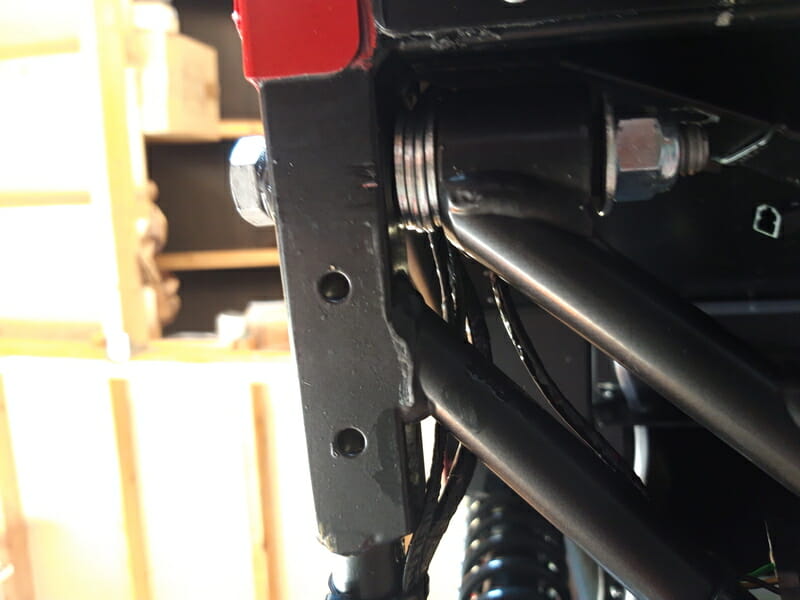
It is a good idea now to have a look at the rear of the car from underneath and apply a brief Hammerite touch up to any damage/scratches to the chassis/components.
Once the paint is dry, now that the de dion, A frame, radius arms and rear dampers have all been done, it is time to torque the components. You want to do this with load going through them. Move the trolley jack to the back of the car, and get it in position just underneath the point where the A frame is bolted to the de dion tube.
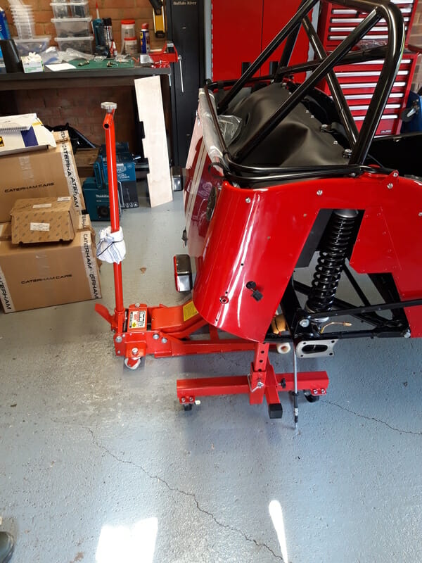
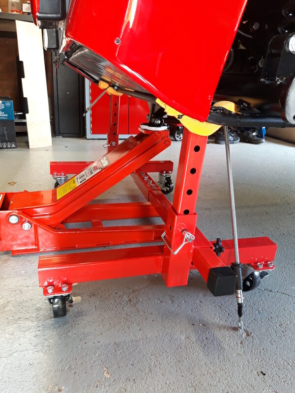
This is your rear jacking point. Jack the car up. Now move the mobile axle stands forward, from the rear chassis rail to underneath the de dion tube. Take care to make sure that they don´t foul on any part of the de dion tube, there should be enough space. Now you have load going through the rear suspension, you can torque and mark all relevant bolts as per the manual.
